Choosing a common rail test bench means deciding which repair jobs your workshop can inspect, measure and verify with confidence. Injector delivery, return flow, pump output, electrical behavior and coding answer different questions. A useful machine package brings those measurements together with the correct fixtures and test data for the components you service.
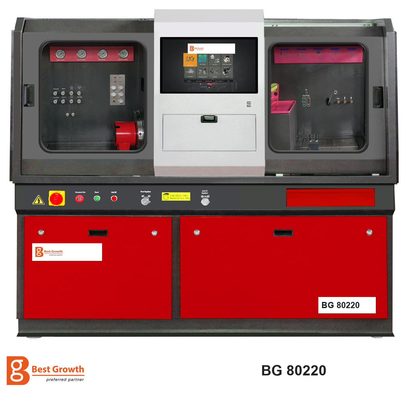
The BG 80220 is a common rail injector and pump test platform with a central operator screen and enclosed working areas arranged on either side. It can be configured around a workshop's injector and pump applications, including additional functions for more demanding component families. Its purchasing value lies in matching that configuration to real work, then producing understandable results for technicians and customers.
BG 80220 equipment overview with BG branding. The final machine specification and accessories follow the agreed configuration.
Start with the repair work you want to accept
A workshop testing passenger-car injectors has different priorities from a service center receiving commercial-vehicle injectors, six-pin applications and pumps requiring separate lubrication. The BG 80220 should therefore be specified from a component list and a test requirement, not from pressure capacity alone.
The equipment platform provides common rail injector and pump testing. Available configuration choices include Denso six-pin injector precision testing, a lubrication function, pump-component testing, a four-injector testing arrangement with newer fixtures, and extensions for Bosch CP5 and Denso HP5, HP6 and HP7 pumps. These are configuration items to define in the quotation and acceptance demonstration, rather than features to assume are included in every machine.
An EUI/EUP upgrade route is also available. Electronic unit injectors and unit pumps require their own mechanical drive and control arrangements; they are not tested simply by selecting a common rail injector menu. Confirm the complete upgrade package if those systems are part of your service plan.
What the injector tests reveal
Delivery quantity and operating-point performance
A complete injector evaluation measures fuel delivery at several defined conditions. Small-quantity points examine behavior in a different part of the operating range from higher-delivery points. An injector that meets a full-load limit can still require attention at a small-quantity point.
The BG 80220's value in this process is the ability to run the selected sequence and compare measurements with the relevant application limits. The technician can see whether the deviation is isolated or repeated across the profile. That supports a more focused repair investigation and a meaningful final retest.
Return quantity and hydraulic condition
Return flow must be measured through the specified adapter and evaluated under the correct conditions. It contributes information about the injector's internal hydraulic behavior, while nozzle delivery describes the useful output at that test point.
A high return value is a reason to investigate, not a complete diagnosis of a named internal part. Before making a repair decision, check collector sealing, return connections, temperature, pressure stability and the selected test plan. This discipline helps prevent setup faults from being presented to a customer as component failure.
Electrical behavior and response
Electrical measurement functions and injector current-curve display add information about actuation behavior. Depending on the application and enabled configuration, resistance, inductance, capacitance and response-related measurements can supplement the hydraulic results.
These functions have different purposes. A coil measurement concerns an electrical property. A drive-current trace shows behavior during electrical actuation. A response measurement concerns the event defined by the relevant procedure. None of these alone proves that delivery quantity is correct at every required point.
For Denso six-pin work, specify the dedicated test function and matching connection kit. Pin count and connector appearance are not enough to establish compatibility. A useful acceptance test uses the exact injector references your workshop plans to service.
Specialized MDP and nozzle-opening functions
For supported applications, specialized functions include MDP and nozzle-opening-related tests. Their value is the ability to investigate specific injector characteristics beyond a routine delivery sequence. The selected procedure must define the measured event, units and limits; a function name alone is not sufficient to interpret its result.
These functions are useful only with the matching application, measurement method and enabled equipment. Ask the demonstration technician to identify what the selected function measures, its units and its acceptance limits. This avoids confusing an electrical response result, a hydraulic delivery result and a nozzle-opening characteristic merely because they appear in neighboring tabs.
Compensation coding
Where supported for the selected injector, coding forms a separate stage of the service process. The injector must first satisfy the required condition and measurement procedure. The applicable compensation code then records characteristics used by the corresponding engine-control strategy.
Ask BG to confirm code generation for your exact injector numbers and required formats. A coding menu is not a promise that every injector from a named manufacturer is supported. Vehicle ECU entry remains a separate diagnostic operation after component testing.
What four-injector testing changes
A four-injector testing configuration with updated fixtures can be specified for the BG 80220. For workshops receiving complete sets, this can organize set testing and comparison within one equipment workflow. Each injector still needs an individual identity and an attributable result.
During preparation, record the cylinder or customer reference for each unit and match it to the installed position or measurement channel. At the end, review every injector against the same applicable limits. A set average must not conceal one unit outside specification.
Before ordering this configuration, confirm the injector families supported in the four-position arrangement, the measurement sequence, the return-flow connections and the format of the individual reports. The number of mounting positions alone does not establish a fourfold reduction in test time. Ask for a complete timed demonstration using a representative set.
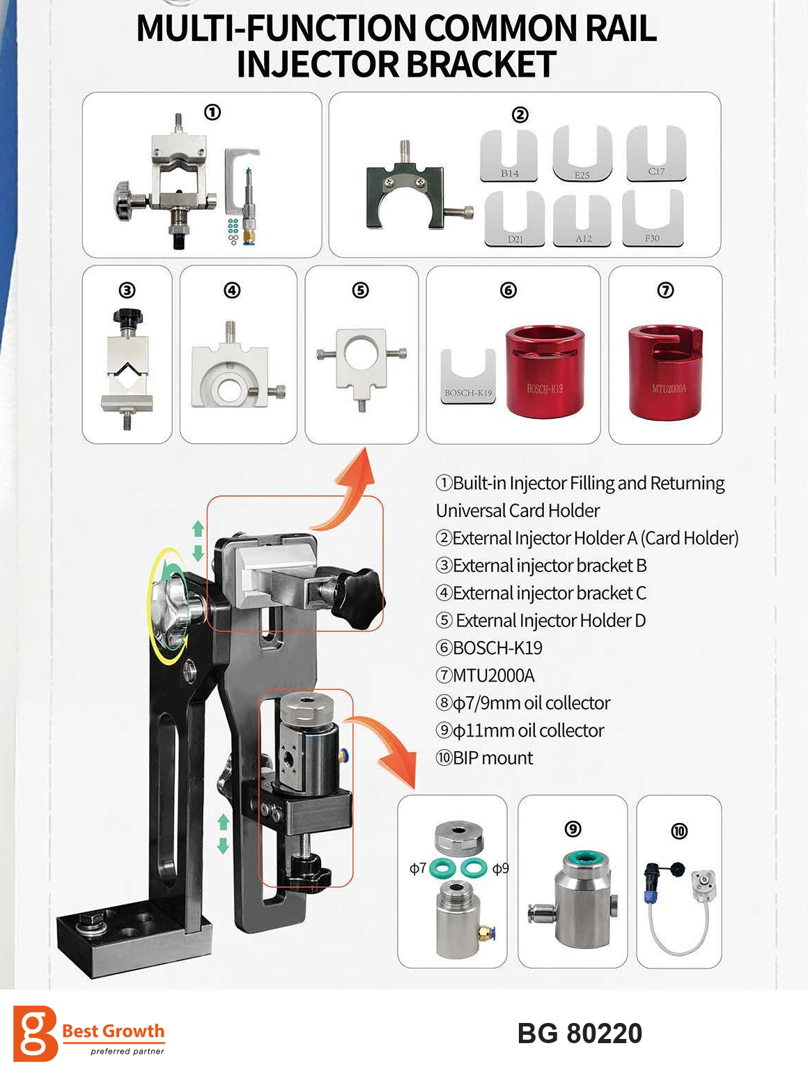
The injector fixture and its adapters are part of application coverage. This reference shows holder and collector options; it does not depict the complete four-injector configuration or establish that every accessory is supplied as standard.
Understanding the workflow from arrival to final report
Receive and identify. Record part numbers, injector positions where relevant and the reported vehicle symptom. Inspect and clean components externally before installation. A bench result is strongest when it can be traced to the exact component received.
Select the correct application. Verify injector technology, pump family, software reference and test-plan version. Match the holder, collector, coupling, return adapter and harness to the component. Do not substitute a similar-looking reference to obtain a result.
Establish the test conditions. Check the specified calibration fluid, filter condition, temperature and level. Complete the prescribed priming or air-removal procedure. For an application requiring separate lubrication, verify that circuit before driving the component.
Run the prescribed sequence. Close the protective enclosure and use the approved operating procedure. Allow stabilization at each required point. If investigating an abnormal result in single-step operation, preserve the full test sequence for the final assessment.
Review, repair and retest. Read delivery, return and supported electrical/response information together. Correct installation issues before repeating a test. After service, retain the completed report with component identity, test conditions and the result at each required point.
Only trained personnel should operate the equipment. Stop and depressurize using the prescribed procedure before touching high-pressure connections, and keep clear of rotating drive assemblies. Specific pressures, torques, fluid grades and connection instructions must come from the approved application procedure.
Pump testing and the importance of lubrication
For a common rail pump, the key question is whether delivery meets the selected limits across the required combinations of drive speed, pressure and valve command. A pump can behave differently during a starting-condition test and a higher-demand point, so a single pressure reading is not a substitute for a full test.
Mechanical alignment, coupling selection, direction of rotation, inlet supply and return routing all affect the validity of the result. Valve-control connections must also match the pump. Where separate lubrication is required, the equipment configuration needs the appropriate circuit and procedure; fuel supply must not be assumed to serve every lubrication requirement.
The BG 80220 can be configured for pump-component testing and extended CP5 and HP5/HP6/HP7 applications. Confirm what is measured in each requested component test, which adapters and controls are included, and which part numbers have valid test data. A list of adapter families is a starting point for specification, rather than proof that every variant has been validated.
Understanding the software during a test
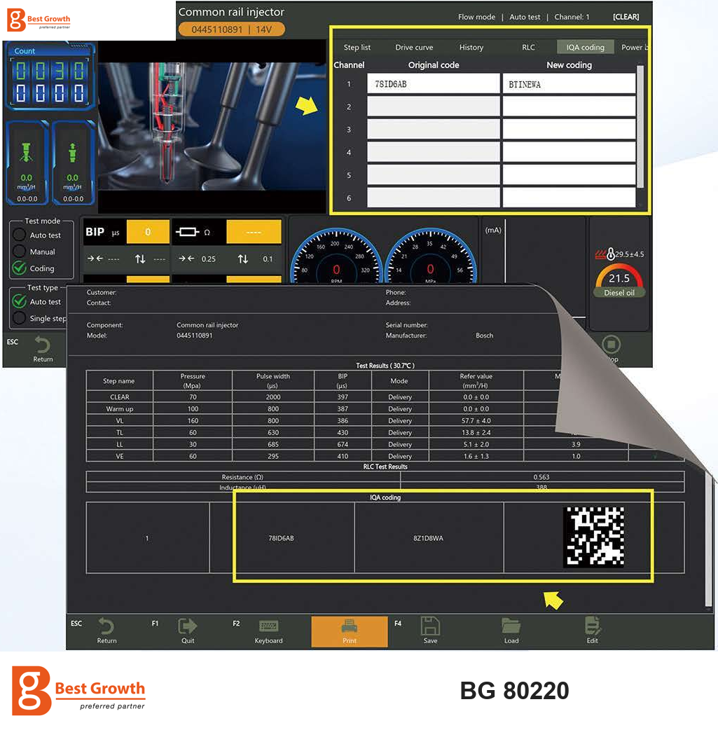
Injector coding and report example from the BG 80220 reference material, with localized BG branding. The displayed values and codes are examples for that component; enabled functions depend on the ordered software configuration.
The software layout connects four types of information. The application header identifies what is being tested. The test-result table records the sequence, pressure, command pulse width, response information and relevant quantity values. Live gauges and channels show conditions such as speed, pressure and fluid temperature. The coding and report controls provide fields for supported compensation codes and functions for printing or saving the job result.
The illustrated report identifies the component and includes hydraulic test points, an electrical-results section and a coding section. These sections answer different questions and should be reviewed separately. Values, codes and limits on the example belong to that component and test plan; they must not be copied as universal settings or assigned to another injector.
During an acceptance demonstration, compare the live injector screen with the final report. Check whether delivery and return are individually attributable, which response or electrical results appear, and how an incomplete step is recorded. The report should also make it possible to associate a generated code with the injector that was actually tested. This is more useful for training and customer explanation than a screenshot showing only a green symbol.
Pressure capacity should match the application
The reference specification lists a rail-pressure range up to 2,700 bar. A separate configuration description identifies a 2,800-bar upgrade. The higher figure applies only to a machine package explicitly specified for it, together with the appropriate pressure-rated circuit, accessories and supported applications.
In either case, testing follows the component's approved operating points. An injector should not be tested at the bench's maximum merely because that pressure is available. For buyers, pressure capability matters when the intended component requires it; the ability to measure and control the correct test conditions remains essential.
How to assess the BG 80220 before purchasing
The BG 80220 deserves a closer look if your workshop wants to combine injector and pump services, handle sets of injectors through an organized process, or add specific applications such as six-pin injector testing or pumps with lubrication requirements.
Use a representative component set for the acceptance demonstration. Ask to see installation, application selection, stabilization, the complete sequence and individual reports. Include the most difficult reference you expect to service, rather than only a familiar demonstration component.
Your configuration discussion should cover:
- Exact injector and pump part numbers and required coding formats.
- The four-injector arrangement and individual-result traceability, if requested.
- Dedicated harnesses, fixtures, pump adapters and lubrication equipment.
- Agreed pressure capability, electrical supply and motor configuration.
- Test-data availability, update arrangements, training and report output.
A 380 V configuration is described for this equipment package; the final electrical specification must match your installation. Confirm the complete machine package rather than inferring it from a brochure option list.
Send BG your component list, local electrical supply and intended service scope. Discuss a BG 80220 configuration and request a demonstration focused on the jobs you want to bring into your workshop.