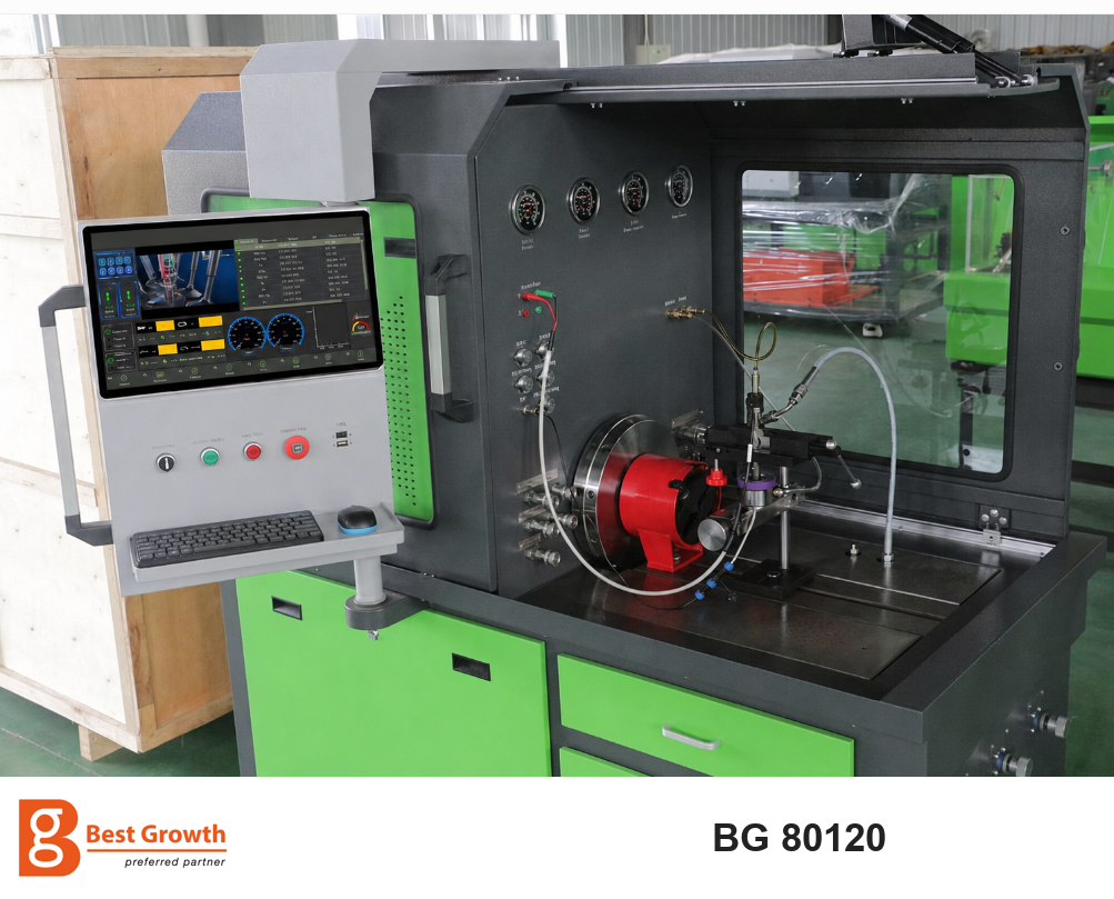
A diesel injection workshop needs more than a reading that says a component passed. It needs to understand how an injector delivers fuel at different operating points, whether return flow is within specification, and whether a high-pressure pump can supply the required delivery under controlled conditions. The BG 80120 brings common rail injector and pump testing into one workshop platform, with an accessible test area and a software interface that connects the selected component to its test sequence.
For workshops servicing both injectors and pumps, its practical attraction is the ability to investigate the two sides of a common rail system using the appropriate fixtures, electrical connections and test plans. That makes it useful for incoming inspection, repair diagnosis and verification after service.
BG 80120 equipment overview. Branding has been prepared for BG presentation; equipment appearance and supplied accessories depend on the ordered configuration.
What can the BG 80120 test?
The BG 80120 supports solenoid and piezoelectric common rail injector testing, with coverage for selected Bosch, Denso and Delphi applications and CAT 320D injector applications. Bosch four-pin and Denso six-pin applications can also be included with the matching equipment configuration. Exact part-number coverage requires the correct software data, harness and fixture; a brand name alone is not a compatibility check.
For common rail pumps, the application scope includes Bosch CP1, CP2, CP3, CP4, CB18 and CB28 families; Denso HP0, HP3 and HP4 families; and selected Delphi and Siemens applications. Mechanical adapters and couplings form part of the pump test setup. A pump that appears in a software menu still needs the correct drive, fluid connections and electrical control arrangement.
Special systems should be discussed as separate configurations. A menu entry for EUI/EUP, a specialized pump or another injection technology does not establish that its required hardware is supplied with every BG 80120. Build the equipment package around the components your workshop actually receives.
What injector testing tells the technician
Injection quantity across several operating points
An injector can behave acceptably at one condition and fall outside its limits at another. A useful test therefore follows the component-specific sequence, which may include small-quantity, idle, intermediate and higher-delivery points. Rail pressure, electrical command duration and test conditions change according to the selected plan.
The measured quantity is compared with the permitted range for each point. This gives the technician a delivery profile instead of a single flow figure. A problem concentrated at small quantities calls for a different investigation from a broad delivery error throughout the sequence. The test indicates where performance differs; further inspection is needed to identify the internal cause.
Return flow and leakage assessment
Fuel returning from an injector must be evaluated separately from fuel delivered through the nozzle. Excessive return flow can indicate an internal hydraulic problem, but the conclusion depends on the injector design, pressure, temperature and return conditions specified by the test plan.
Reading delivery and return together is more informative than reading either alone. Low delivery with excessive return is a different pattern from low delivery with return inside the expected range. Before condemning the injector, verify that the collector seals, return adapter, hose routing and measurement connections are correct.
Response measurement and electrical checks
Where the selected configuration and application support them, response measurements and electrical checks provide another layer of information. BIP-related response results concern the measured switching event defined by that test procedure; they should not be treated as a direct measurement of every stage of fuel injection.
Resistance and inductance are relevant to supported solenoid applications. Additional checks for piezoelectric applications depend on the installed equipment and application procedure. These checks help distinguish an electrical concern from a hydraulic delivery concern. The available measurements, leads and procedures must match the injector technology. They are not interchangeable tests.
Coding after a successful repair
The software platform includes coding functions for supported applications. A compensation code describes measured injector characteristics for the relevant control strategy. It is produced through the appropriate measurement and coding procedure; it does not repair a worn injector or turn a failed hydraulic result into a satisfactory one.
Before offering a coding service, confirm the exact injector reference, code format and enabled software function. Writing the resulting code into a vehicle control unit is a separate vehicle-service operation using suitable diagnostic equipment.
Turning measurements into a useful repair decision
| Observed pattern | What it tells the workshop to investigate |
|---|---|
| Higher-delivery points pass but small-quantity points fail | Review performance in the low-delivery region; one successful high-delivery result is insufficient |
| Delivery is low and return is excessive | Verify the setup, then investigate internal hydraulic loss using the approved repair procedure |
| Electrical results are abnormal | Check the harness and connections, then evaluate the relevant electrical element before hydraulic conclusions |
| Repeated measurements vary widely | Check temperature, air, pressure stability, sealing and measurement condition before adjusting the component |
These are diagnostic directions rather than unique fault identifications. The value of the bench is that it makes the pattern visible and gives the technician a repeatable basis for the next check.
Understanding an injector test workflow
1. Identify and inspect the component. Record the complete part number and customer complaint. Inspect the inlet, nozzle, electrical connector and return connection. Clean the outside before installation, and keep contamination out of the test-fluid circuit.
2. Match the application data and hardware. Select the correct injector type and reference. Fit the specified holder, collector, return adapter and harness. Confirm the permitted test pressure and return arrangement for that application rather than using the bench's maximum pressure as a default.
3. Prepare the fluid and measurement conditions. Check the specified calibration fluid, level, filtration and temperature. Prime or bleed the circuit using the equipment procedure. Inspect the assembly for leakage with the system in the prescribed preparation state.
4. Run the complete test plan. Close the protective enclosure before pressurization. Allow the required stabilization, then run the automatic sequence. Use a supported single-step function for investigation when appropriate, while retaining the full sequence for the final assessment.
5. Review the pattern and document the result. Compare delivery, return and available response results at each applicable point. If a result is inconsistent, check installation and test conditions before repeating it. After repair, rerun the required sequence and retain the before-and-after record.
High-pressure connections must only be handled after the prescribed stop and depressurization procedure. Hands and tools must stay clear of rotating assemblies. This workflow explains the method; the supplied operating instructions define the exact connection, tightening and safety requirements.
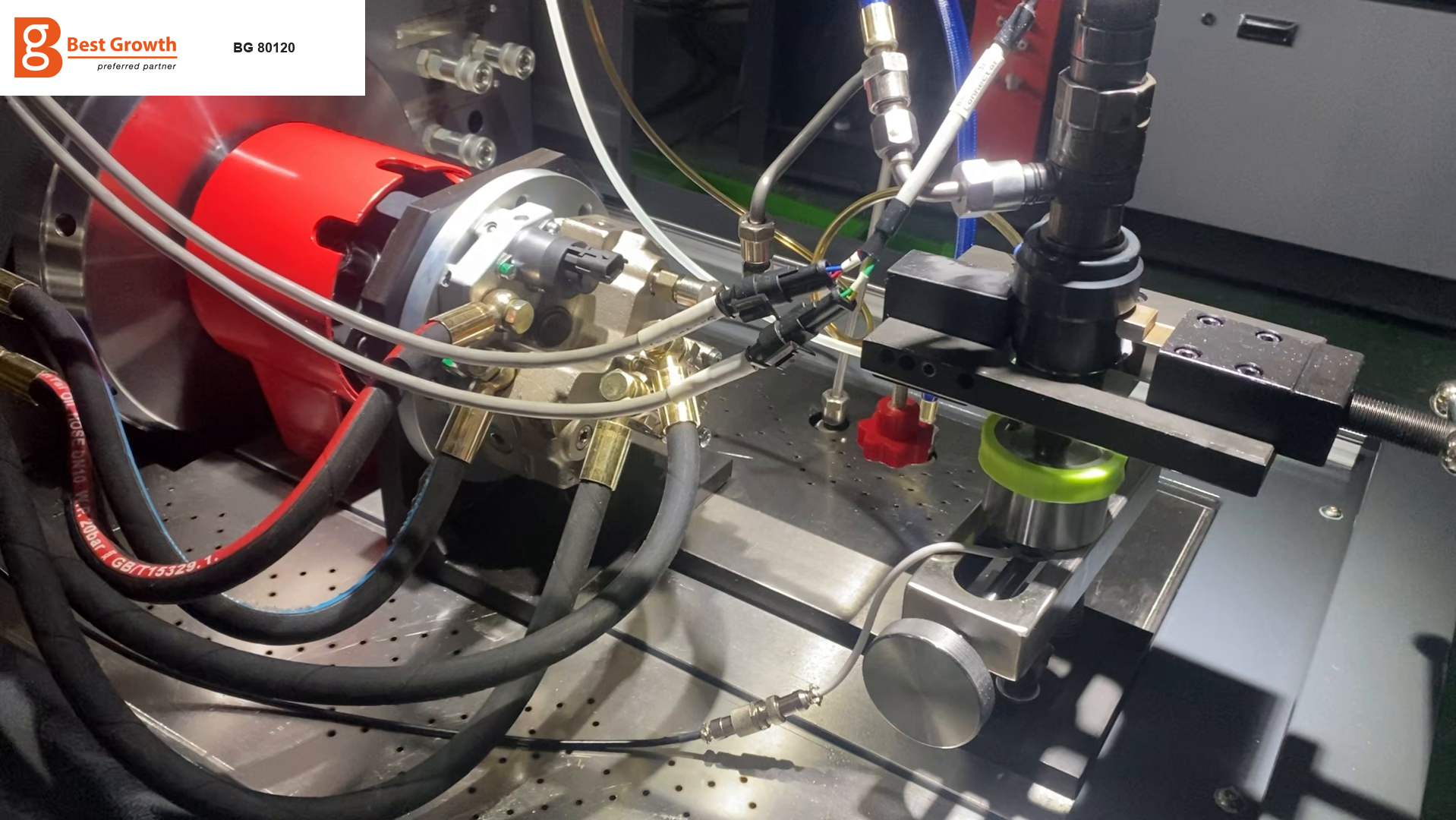
A video-derived setup example shows the relationship between the drive coupling, test component, fixtures and hoses. The illustrated arrangement is application-specific and is not a universal connection diagram.
How common rail pump testing works
Pump testing asks a different question from injector testing: can the pump deliver the required quantity at the specified speed, pressure and control condition?
The technician first matches the mounting flange and drive coupling to the pump. Rotation direction, alignment, supply and return connections, valve control and any separate lubrication requirement must follow the selected application. These details matter because a setup error can resemble a defective pump.
The software demonstration includes steps labelled Warm up, Start test, Zero delivery, Full test and Efficiency. These are application-specific test points. A starting-condition point examines delivery under its defined low-speed condition. Higher-delivery points evaluate supply under a different demand. A zero-delivery point evaluates behavior under the corresponding control command. A step called Efficiency should be interpreted according to its test-plan definition; its name alone does not establish a universal percentage efficiency measurement.
The result is a profile across operating conditions. If delivery is low, the technician should first check fluid supply, air, filtration, rotation and electrical actuation. Persistent deviation under correct conditions supports further pump investigation. One screen reading cannot independently distinguish every possible pumping-element, metering-valve or internal-leakage fault.
Reading the operator interface
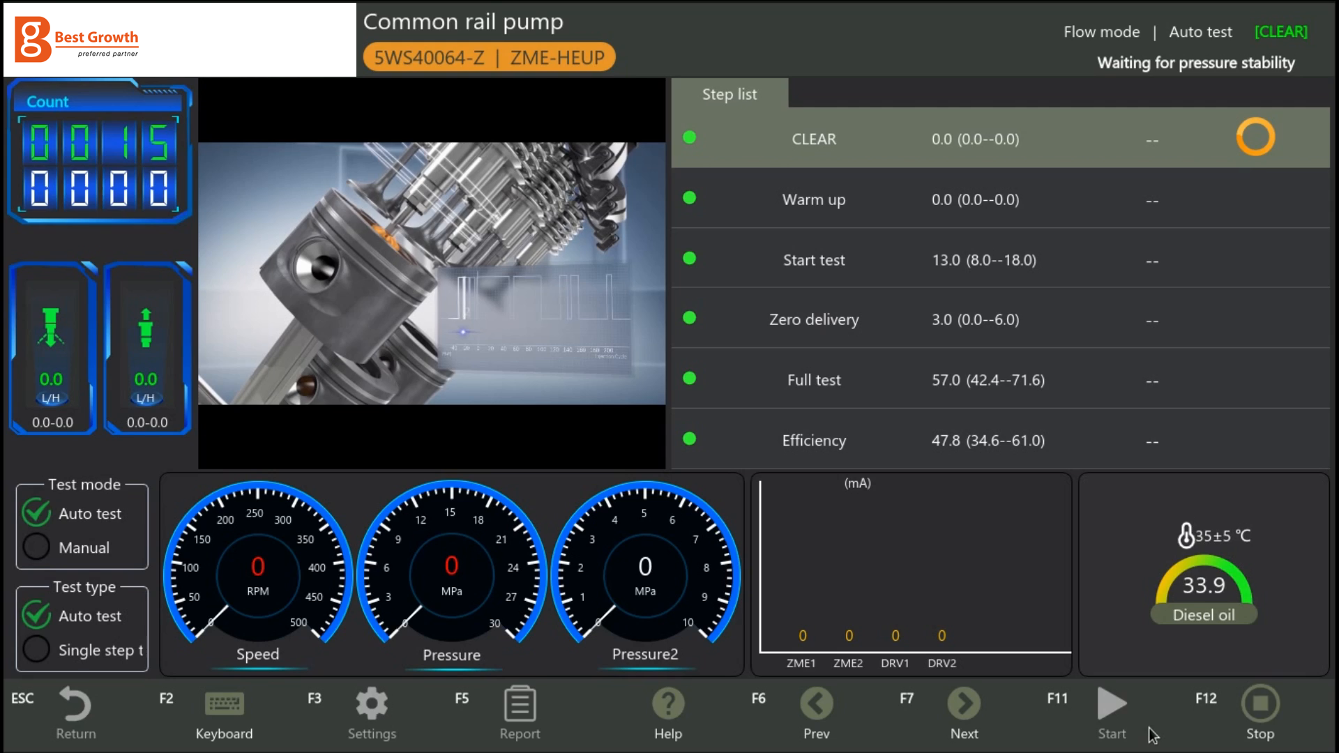
Pump test interface extracted from the supplied demonstration video and prepared with BG branding. The displayed numbers describe that example and must not be used as universal settings or acceptance limits.
The screen groups the information a technician needs during a run:
- Application header: the selected pump reference and control type. Check these before starting.
- Step list: the current operation, nominal values or permitted ranges, and the result/status area. A target value is not the same as a measured result.
- Live measurements: speed, pressure, flow and fluid temperature, with additional channels where the application uses them.
- Control outputs: displayed actuator currents or channels, useful for understanding the command applied during the measurement.
- Operating controls: automatic/manual selection, single-step operation where enabled, Start, Stop, Settings, Help and Report.
The example screen is waiting for pressure stability. Empty result fields at this stage do not mean the component passed or failed. The useful report is the completed sequence with the relevant operating conditions and result for each required point.
Why the physical layout matters in daily work
The BG 80120 layout combines a broad test area, a drive assembly and an operator console positioned beside the working zone. The operator console can be positioned alongside the working area. For a technician changing between pump adapters, injector holders and harnesses, visibility and physical access matter as much as the number of software functions.
Storage drawers help keep frequently used adapters close to the machine. The value of this arrangement depends on organizing them by application and protecting sealing surfaces and connectors. A comprehensive adapter inventory is useful only when the technician can identify and install the right part consistently.
Technical points to include in your equipment specification
| Item | Reference capability or purchasing requirement |
|---|---|
| Injector technologies | Supported solenoid and piezoelectric applications with matching data and connections |
| Pump applications | Selected Bosch, Denso, Delphi and Siemens families with the correct adapter package |
| Coding and response functions | Specify the exact injector references, enabled functions and required accessories |
| Electrical installation | Confirm voltage, phase, frequency and motor configuration for the delivered machine |
Pressure capability, drive speed and display specification must be confirmed for the agreed BG 80120 configuration. Temperature control, filtration, measurement verification and the correct calibration fluid are part of obtaining useful results; maximum pressure alone does not establish measurement quality.
Is the BG 80120 suitable for your workshop?
The BG 80120 is worth evaluating when your workshop receives both common rail injectors and high-pressure pumps and wants to build a documented diagnosis-and-retest process. It is particularly relevant when your daily work includes several component families and frequent fixture changes.
Evaluate it against a list of actual part numbers, rather than a broad request to test every diesel system. Ask for a demonstration that includes component identification, installation, a complete test sequence and the resulting report. For coding or specialized response measurements, include those exact requirements in the demonstration.
For a configuration recommendation, send BG your most frequently serviced injector and pump references, required coding functions, local electrical supply and expected workload. Contact BG about the BG 80120 to discuss the equipment, adapters and software scope needed for those jobs.